|
|
|
|
 |
|
 |
|
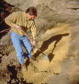
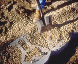
| STEP ONE: Prepare the base leveling pad. |
|
| Remove all surface vegetation and debris. Do not use this material as backfill. After selecting the location and length of the wall, excavate the base trench to the designed width and depth. Start the leveling pad at the lowest elevation of the wall. Level the prepared base with 6" of well-compacted granular fill (gravel, road base, or 1/2" to 3/4" [13 - 20 mm] crushed stone). Compact to 95% Standard Proctor or greater. Keystone recommends additional trench depth for below grade placement of Keystone units on a ratio of 1" (25 mm) below grade for each 8" (200 mm) of wall height above grade (to a maximum of 3 units buried). This lowers the base course below grade locking the wall in place and also helps prevent erosion and scouring at the base of the wall. The base trench should be wide enough to allow for the Keystone unit and drainage zone. An option to a compacted, granular material leveling pad is to use a non-reinforced concrete leveling pad. In some cases, contractors find this is a time-saving approach. Walls built to a level condition on a sloping grade require a stepped base. It is best to work out the stepped base as the wall steps up in elevation. If a concrete leveling pad is used, the step-up height needs to exactly match the Keystone unit height. |
 |
 |
|
|
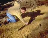
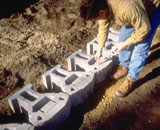
| STEP TWO: Install the base course. |
|
| Place the first course of Keystone units side by side (with sides touching) on the prepared base, with the paired pin holes facing up. Make sure each unit is level — side to side and front to back. The first course is critical for accurate and acceptable results. For alignment of straight walls, use the pins or the straight back edge of the unit. Using the front face will give irregular alignment due to the rough split texture. For constructing curved walls, use the front pin position for best results. Minimum radius for convex and concave curves is 3'6" (1 m). |
 |
|
|
| STEP THREE: Insert the interlocking fiberglass pins. |
|
| Place the reinforced fiberglass pins into the paired holes (2) of each Keystone unit. (Pins of adjoining units should be 12" [305 mm] on center.) Once placed, the pins create an automatic setback for the additional courses. According to wall requirements and design, place pins in the front holes for near vertical (1/8" or [3 mm]) setback and the rear holes for 11/4" (32 mm) setback per course. |
 |
|
|
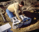
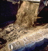
| STEP FOUR: Install and compact backfill and corefill material. |
|
| Fill in all voids — in and between Keystone units — using 1/2" to 3/4" (13 - 20 mm) crushed stone or clean, well-draining granular fill. Place drain zone behind the units as required to achieve total 2 ft. (0.6 m) depth of drainage zone from unit face. Peagravel should not be used. Compact material in unit cavities appropriately to eliminate settling. Next, if economical, use existing soils for backfill behind the gravel drainage zone. (Heavy clays or organic soils are not recommended due to water-holding properties.) In some situations poor site soils will cause higher reinforcement costs, so economics of using import soils should be reviewed. Compact soils to a minimum of 95% Standard Proctor compaction, placing fill in 8" (200 mm) lifts on a course-by-course basis or as specified by a Professional Engineer. (Use only walk-behind mechanical compaction equipment within 3' [1 m] behind the units to avoid localized overstress.) Sweep off any pebbles or debris so the next. Keystone units rest evenly upon the layer below. |
 |
 |
|
|
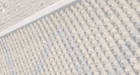
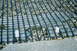
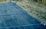
| STEP FIVE: Geogrid Installation |
|
For taller or more critical walls that require use of geogrid, continue the installation process with Step 5. If geogrid is not required, skip to Step 6.
Step 5A. Excavate Reinforced Soil Area. Remove existing soils in the reinforced soil area to the maximum embedment length of the geogrid design. Provide a generally level soil condition behind the wall units for the placement of each geogrid layer.
Step 5B. Cut Geogrid. Cut sections from geogrid roll to the specified length (embedment depth). Geogrid roll direction is from the wall toward the embankment. Check manufacturer’s criteria for biaxial or uniaxial geogrids. In most cases correct orientation is to roll the geogrid perpendicular to the wall face.
Step 5C. Install Geogrid. Hook geogrid over the Keystone fiberglass pins to ensure a positive mechanical connection between the unit and geogrid.
Step 5D. Secure Geogrid. Pull the pinned geogrid taut to eliminate loose folds. Stake or secure back edge of geogrid before and during backfill and compaction. Remove stakes, if desired, once backfill is placed. Place additional sections of geogrid, abutting each other, for continuous coverage at each layer.
Step 5E. Install Next Course of Keystone Units.
Step 5F. Place Compacted Backfill Over Geogrid In 8" Lifts. Provide a minimum of 6" (150 mm) reinforced fill coverage prior to driving equipment over the geogrid with tired equipment. Avoid driving or turning vehicles directly on geogrid to avoid excessive damage. |
 |
 |
|
|
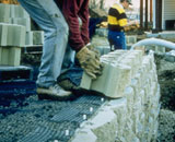
| STEP SIX: Install additional courses. |
|
| Place the next course of Keystone units over the fiberglass pins, fitting the pins into the kidney-shaped recesses. Center the unit over the two underlying units as shown.Visually sight down in the kidney-shaped recess for pin positioning. Pull the Keystone unit toward the face of the wall until it makes full contact with both pins. For each remaining course, repeat Steps 3-6. |
 |
|
|
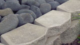
| STEP SEVEN: Install Keystone cap units. |
|
| Complete your wall with Keystone Caps (see options on page 4). In areas of high public usage, apply Keystone KapSeal™ (a construction adhesive for masonry units) on the top surface of the last course before applying cap units. Place the Keystone Cap unit over the pins on the underlying unit. Pull the Cap unit forward to the automatic setback position. Backfill and compact soils behind wall to finish grade. Finish grade with appropriate plastic soil cap or drainage swale to minimize surface water flow into wall/soil structure. |
 |
|
|
|
|
|